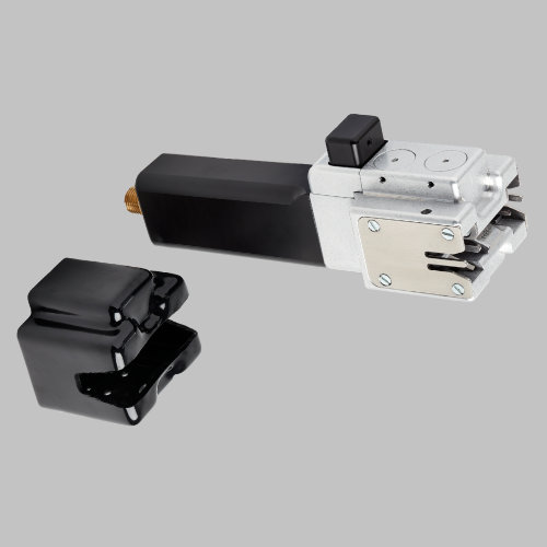
Product Specification
Splice format: Ends opposed
Applications: All standard textile processes – weaving, warp knitting, knitting etc.
Yarns: Nylon, Polyester, fine glass fibre, aramid, Dyneema, Nomex etc..
Yarn counts:Nm .5 to 100, 10 to 2000 tex.
Twist: Zero or low twist c.f. and chopped-strand.
Model 111 for composites
Please see the new model here
The multi-purpose splicer for low-count yarns for composites
The 111 sets the standard as an effective splicer for difficult synthetics used in the manufacture of composites. It’s tough, reliable, and easy to maintain, handling a wide range of yarn counts.
The 111 fills the low-range composites niche perfectly. It’s available in different forms – with handles, with a hanging device to be used in a fixed position, or with a carriage for sliding along a rail. There’s a blast timer, or a flow control system for varying air pressure to the blast chamber. Any form of 111 can be converted to another.
Using the Model 111
The 111 Series makes joints of the form known as “ends-opposed”, the classic form of splice. The ends-opposed splice is described in more detail elsewhere.
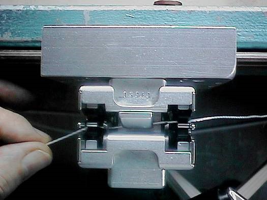
The first yarn is placed in the splicer. It enters from the right-hand side, via the upper right clamp, and leaves via the lower left clamp.
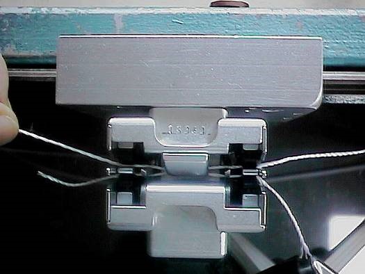
The second yarn is placed in the splicer. The yarn enters via the upper left clamp, and leaves via the clamp at lower right. Note the flat “X” form of the string-up.
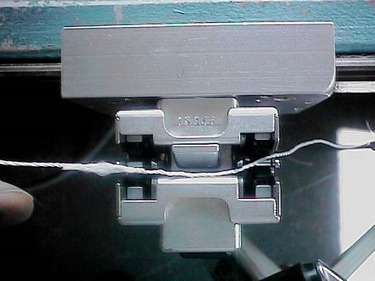
Press the trigger in one swift, single movement.
If the splicer has no timer, press the trigger for a chosen blast period; then release it. Bit iIf the splicer has a timer, press the trigger until the blast ceases. Then release it.Fourth stage: remove the splice
Once the splice is made, the completed joint is withdrawn and the waste ends are discarded. This typical ends-opposed splice has a wide section at the centre, corresponding to the position of the blast hole in the splicing chamber. Just visible in this splice are the “tails” – the cut ends of the yarns project very slightly from the ends of the splice.
Optimising splicing performance – knife timing
All 111 Series splicers can handle a wide range of yarn counts, requiring fewer chambers than most to cover its operating range. This flexibility comes from two design advances – the splicing chamber technology, and the special adjuster built into the trigger. The simple adjuster improves splicer performance; a small wheel in the trigger button is marked with numbers from 0 to 6 which may be “dialled up” according to the user’s needs.
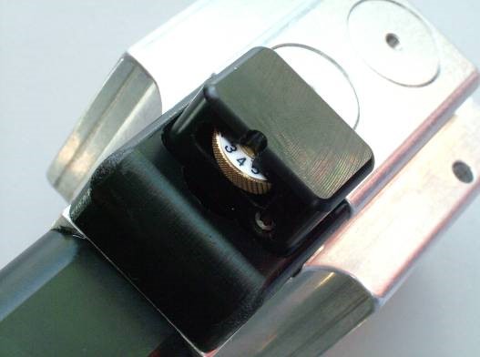
At setting 3, the knife cut is simultaneous with the chamber blast.
At setting 6, the knives cut only after the main chamber blast has already started
The adjuster wheel should be used to optimise the performance of the splicer for a particular application. The best setting for a given application should be found by trial-and-error. Once the best operating position has been found, the wheel then can be secured with a small locking screw which is built into the top surface of the trigger button. The performance of the splicer will then remain consistent.
Interested in the Product? Would like to find out more?


